Summary Part 1
Removal of stock parts Part 2
Wiring Part 3
Aristo engine differences Part 4
Installation Part 5 – You are here
Final thoughts Part 6
So at this stage most of the tedious hard work of any custom wiring is complete and the process of upgrading engine and drive line components should be done at this stage before the engine is installed, which really is just about the last part.
There is so much work that does go into this stage though, especially with the Aristo engine differences, so I’ve added that to Part 4 here – http://www.2jzgarage.com/2016/02/toyota-supra-na-tt-conversion-aristo-engine-differences-part-4. This is where you can find out more info about swapping over parts from the Aristo engine, I suggest that you read this as it also shows some other components that you need to install such as sensors and engine mounts.
I was a little light on with pictures near the end the end of this project as the finishing touches went on as it became very exciting and I just wanted to drive the bloody thing! So apologies in advance for some lack of information and pictures at this stage, but I think those parts are fairly self-explanatory.
Below are some of the new parts I’ve listed as recommend and optional. I do recommend changing as much as you can while the engine is out, this list was the basic one I was willing to change on my 70,000km (43,00mile) Aristo engine and within the budget I had at the time. If I had a larger budget then I would’ve done as much as possible at this stage – please, please, please do the timing belt as a bare minimum!
Recommended parts;
• Timing belt (I prefer aftermarket Kevlar items)
• Cam, crank, rear main seals
• OEM Fuel filter
• OEM Water pump, gasket and seals
• OEM/TRD Thermostat and seals
• OEM TT P/S reservoir
• Supra VVTi throttle cable
• SMIC or FMIC and piping
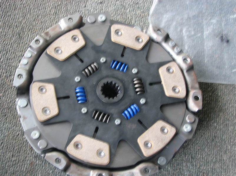
• Clutch and flywheel
• TT Exhaust system
• TT Radiator and hoses
• TT Air intake
Optional;
• Timing belt tensioner
• Timing belt tensioner pulley/bearing (aftermarket billet bracket if possible)
• Harmonic balancer
• Aftermarket cam gears
• Engine gasket kit
• Aftermarket clutch and flywheel
• TT clutch master cylinder heat shroud
• TT electric radiator fan
• Aftermarket FMIC and piping
• Aftermarket radiator
• Aftermarket air intake
• Any engine, turbo or intake plenum upgrades!

Gearbox, clutch and flywheel
Since I’m using the existing V161 6 speed gearbox that came with the SZR all I required was an upgrade to the clutch and flywheel, although not strictly required I figured it was worthwhile upgrading to an aftermarket setup as I had a few mods planned which would require an increase in torque clamping. For those with an NA 5 speed W58 gearbox you will need an upgraded clutch and a speed sensor to suit.
The full list of V160/V161 clutch parts can be found in my article here – http://www.2jzgarage.com/2013/06/toyota-supra-getrag-6-speed-full-clutch-replacement-part-numbers
Clutch diagram

Gearbox removed from the engine


Stock flywheel removed

Stock clutch removed


You can see the snap rings and throw out bearings here
Slave cylinder

Main rear seal and pilot/spigot bearing replaced while the flywheel was out – a perfect time to do this, I’ve also posted a nice little fun way to remove the pilot bearing with, which can be found here – http://www.2jzgarage.com/2012/04/removing-pilot-bearing-without-expensive-tools/ 
Tested the install of the RPS clutch within the gearbox (with new snap rings and throw out bearing)


Installed new flywheel with brand new flywheel bolts – please ensure they are brand new and torqued as per the service manual


I now installed the clutch directly to the back of the engine and flywheel, I lightly did up the clutch pressure plate bolts so that the clutch plate would move into place as I installed the gearbox, alternatively you can use a clutch installation/alignment tool to make it easier.


Gearbox re-installed and clutch pressure plate bolts torqued up


This is also good opportunity while the gearbox is out to clean and lubricate the starter motor as mine was very dirty (no clean pics sorry!)


Cam gear, timing belt and water pump replacement
I decided to replace the cam gear, timing belt, water pump, thermostat and all the seals while the engine was out, for those wanting detailed steps on the cam gear replacement then you can follow my guide here – http://www.2jzgarage.com/2013/06/aftermarket-cam-gear-installation/
To remove the balancer place some old flywheel bolts like this on the flywheel to remove the balancer *Important – these bolts will never be intended to use again as they may bend. You will need a long pipe between to stop them moving while you remove the balancer bolt with a very large air impact socket or a very long breaker bar with a pole for leverage.
*NOTE – As usual with all Supra owners I experienced the “This bolt will never come off” moment, until I learnt a little trick about leverage, go to a local metal place and find a big pole to place over your breaker bar!!!

Harmonic balancer and bolt to remove

Pulley removal tool used to remove balancer from crank snout

Titan cam gear


All removed

Here you can see the timing belt tensioner and pulley, while you are here you can remove the crank pulley and seal to replace the seal (No pictures of the seal sorry).

Timing belt tensioner pulley *Note – I highly recommend replacing this pulley and the tensioner which I’ve done since this conversion

Timing belt removed

Water pump removed


Replace this seal on the block, the seal on the top pipe from the water neck and also the gasket where the pipe mounts to the water pump

New water pump installed


Timing belt back together


Also finally ensure the thermostat and seal are installed in the water pump housing

Clutch master cylinder heat shield
The NA didn’t have a clutch heat shield as standard because there is not 2 turbos generating heat, but the master cylinder did have provisions that could be tapped and have new threads with OEM bolts placed. I purchased an OEM heat shield to protect the clutch master cylinder from boiling it’s fluids with the new TT setup – its small touches like this that make a difference in a quality conversion.


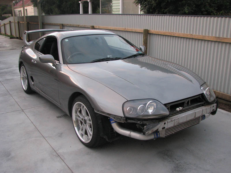
FMIC install
So a little spoiler picture here, but I did mount the engine without the gearbox for a quick test fit with the engine mounts I swapped from the old NA engine and to test fit the FMIC and make sure the piping was all made up to suit. I chose to go with a Blitz 3 row FMIC kit at the time and it came with everything I required.
Alternatively you can mount an OEM SMIC (Side mount) and piping.
I first removed the old P/S cooler

The GReddy kit comes with brackets for the A/C pipe, P/S cooler and water overflow relocation


I mounted the FMIC core and test fitted the piping, this kit also required me to remove the top cooling plate plastics and relocate the bonnet release cables, I put an aftermarket air diversion/cooling plate in later


Engine install
Before you get to installing the engine it’s a great opportunity to clean up the engine bay

Ensure the old P/S reservoir is removed, ensure the new TT one is installed


The engine is all now ready to go in! Make sure the loom is securely positioned and I’d also recommend covering the loom plugs or cable tying them out of the way


Engine Installed!!!!!!!!!!!!


Install driveshaft, do up the differential and gearbox bolts, along with the driveshaft mount and gearbox mount bolts. Don’t forget to install the clutch slave cylinder hard line also.

Ensure that FMIC pipe clamps are securely fastened

Always check spark plugs, these double pronged ones that the engine came with from Japan were fouled and I wasn’t having much luck when I started the engine for the first time, so these were swapped out for fresh BKR6E plugs

Exhaust system
This was a perfect time to upgrade the exhaust system so I took the chance and purchased an Aftermarket dump pipe via Tuneagent and also a 2nd hand full mid pipe/catback system, the catback was a GReddy SP TT exhaust system, ensure the o2 sensor is plugged in.

GReddy SP TT exhaust system


Fuel filter
Ensure that the fuel filter is replaced, mounted and connected to the fuel dampener


Hook up the Idle up hose for the P/S system

Radiator, lower and upper hoses and fan shroud installed before my other parts arrived, along with the VVTi throttle cable and battery/cables

Something I didn’t do as I had an aftermarket radiator planned but can be done is the optional fan found in the TT

Finalising the installation
Ensure that the interior is put back together with the loom plugs, ECU, throttle cable to pedal connection.


At this stage you should be ready to test start the engine, ensuring that everything is idling, running as intended, testing all functions of the engine and electrical systems, check for leaks, top up coolant, engine oil and power steering fluid, bleed the clutch and once you’re happy you can then test drive! 


I had a few small changes to make before I could take for a longer test drive, I installed the front bar, ensured all the lights and indicators were hooked up, installed my final HKS intake system with the AFM sensor and TRD strut brace


New radiator hard pipes and FMIC diversion plate installed to finish off the temporary parts that were left


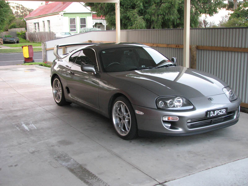
If you’ve made it to this stage then grab yourself a beer, a protein shake or a bottle of water and celebrate!